

optical design
The design of the optical system is to determine various solutions that meet the requirements of the use according to the customer's use conditions, that is, the structural form, performance parameters, and external dimensions of the optical system. We can provide customers with unique, professional, mass-customized optical system design.
|
|
Imaging lens technical index requirement table |
|||
|
|
Serial number |
parameter name |
Parameter value |
Remark |
|
Optical specifications |
1 |
Working distance (mm) |
|
The distance from the front end of the lens to the imaged object |
|
2 |
Structure back focal length (mm) |
|
The distance from the last mechanical end of the lens to the detector |
|
|
3 |
Total distance of object image (mm) |
|
The distance between the imaged object and the detector. This parameter determines the space occupied by the imaging lens for normal operation |
|
|
4 |
System focal length (mm) |
|
|
|
|
5 |
Entrance pupil diameter (mm) |
|
Effective clear aperture during imaging |
|
|
6 |
Working band (nm) |
|
Optical spectrum of lens work |
|
|
7 |
Full field of view ( °) |
|
The fully visible angle of the detected object |
|
|
8 |
Full field of view (mm) |
|
Full view area of the detected object |
|
|
9 |
Sensor size (mm x mm) |
|
Detector target surface size, resolution |
|
|
10 |
Main magnification |
|
Ratio between sensor size and field of view |
|
|
11 |
Zoom magnification |
|
The ratio between the sensor size and the field of view at different working focal lengths of the zoom lens |
|
|
12 |
Transmittance (%) |
|
The attenuation rate of the lens to the intensity of the imaging beam |
|
|
13 |
Relative illuminance (%) |
|
The ratio of peripheral illuminance to center illuminance |
|
|
14 |
Optical function MTF (%@lp/mm) |
|
Resolvable line contrast per 1mm |
|
|
15 |
distortion(%) |
|
The ratio of the height difference between the off-axis beam imaging point and the ideal imaging point to the height of the ideal imaging point |
|
|
Interface requirements |
16 |
Total length of lens (mm) |
|
|
|
17 |
Entrance pupil position (mm) |
|
The distance between the entrance pupil of the lens and the mechanical end face of the lens |
|
|
18 |
Entrance pupil size (mm) |
|
Lens entrance pupil diameter |
|
|
19 |
Maximum diameter (mm) |
|
|
|
|
20 |
Weight (kg) |
|
|
|
|
Environmental requirements |
21 |
Working temperature requirement ( °C ) |
|
Ambient temperature range when the lens can work normally |
|
22 |
Storage temperature requirements ( °C ) |
|
Lens storage environment temperature range |
|
|
23 |
Vibration (g) |
|
The maximum vibration acceleration that the lens needs to withstand during normal operation |
|
|
24 |
Impact (g) |
|
The maximum shock acceleration that the lens needs to withstand |
|
|
25 |
Other environmental requirements |
|
Humidity, acidity and alkalinity, airtightness, etc. |
|
The optical design process is divided into four stages: shape size calculation, initial structure calculation, aberration correction and balance, and image quality evaluation.
1. Dimensional calculation
Design and draw up the principle diagram of the optical system, determine the basic optical characteristics, and meet the given technical requirements, that is, determine the magnification or focal length, line field of view or angular field of view, numerical aperture or relative aperture, conjugate distance, back working distance Diaphragm position and dimensions, etc. The mechanical structure and electrical system must be considered in the calculation to prevent it from being impossible to achieve in the structure of the mechanism. The determination of each performance must be reasonable, too high requirements will make the design results complex and waste, and too low requirements will make the design not meet the requirements.
2. Calculation and selection of the initial structure
The following two methods are commonly used to determine the initial structure:
1. Solve the initial structure according to the primary aberration theory
2. Select the initial structure from the existing data
This is a more practical and easy way to achieve success. However, it requires designers to have a deep understanding of optical theory and rich design experience. Only in this way can a simple and satisfactory initial structure be selected from a wide variety of structures. A bad initial structure, no matter how good an automatic design program and an experienced designer can make the design successful.
3. Aberration correction and balance
After the initial structure is selected, use software such as ZEMAX and CODEⅤ to analyze the optical system and trace the optical path to calculate all aberrations and various aberration curves. From the analysis of aberration data, it is possible to find out which aberrations mainly affect the imaging quality of the optical system, so as to find out ways to improve and start the aberration correction. Aberration analysis and balance is an iterative process until the image quality requirements are met.
4. Image quality evaluation
The imaging quality of the optical system is related to the size of the aberration, and the purpose of optical design is to correct the aberration of the optical system. However, it is impossible and unnecessary for any optical system to correct all aberrations to zero. There must be residual aberrations. Different sizes of residual aberrations result in different image quality. Therefore, the optical designer must understand the allowable value and aberration tolerance of various optical systems in order to judge the image quality of the optical system according to the magnitude of the residual aberration. There are many methods to evaluate the image quality of an optical system. The following briefly introduces the method of image quality evaluation.
1. Rayleigh's judgment
The maximum wave aberration between the actual wavefront and the ideal wavefront does not exceed 1/4 wavelength. It is a stricter image quality evaluation method, suitable for small aberration systems such as telescopes, microscope objectives, etc.
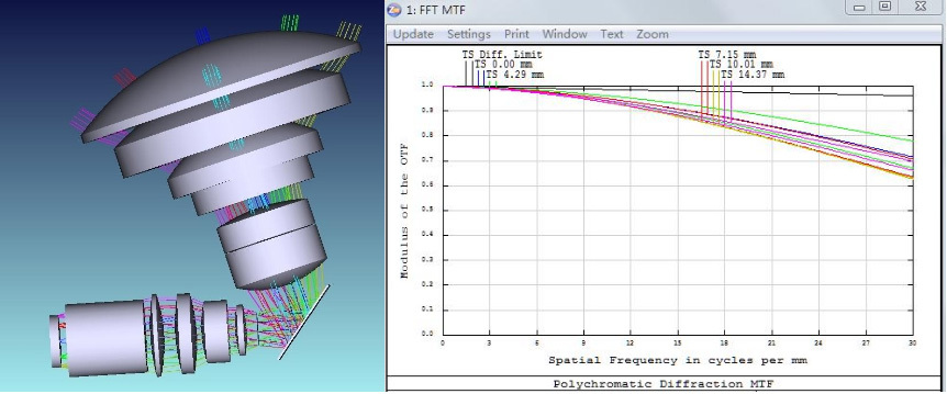
2. Optical transfer function MTF
This method is based on viewing objects as composed of spectra of various frequencies. The optical system is regarded as a linear invariant system. In this way, the image of an object through the optical system can be regarded as the transmission of a series of sinusoidal distribution linear systems with different frequencies. The characteristic of the transmission is that the frequency remains unchanged, but the contrast decreases. The decrease in contrast and the shift in phase vary with frequency, and the functional relationship between them is called the optical transfer function. Since the optical transfer function is related to aberration, it can be used to evaluate the imaging quality of the optical system. It has the advantages of objectivity and reliability, and is easy to calculate and measure. It can not only be used to evaluate the results of optical design, but also control the process of optical system design, lens inspection, and overall optical design.
Testing Services


 No.82 Fengze Road, Jiangning, Nanjing City, Jiangsu Province
Copyright(c)2024 Nanjing wave front optoelectronic technology co. LTD. All Right Reserved Powered by:300.cn
