

Optical foundation
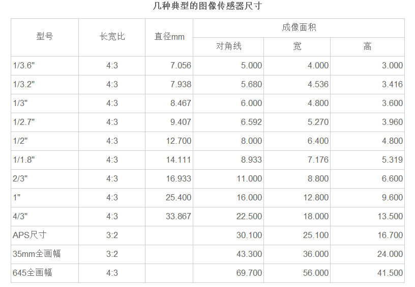
1. CCD size
actually refers to the area size of the photosensitive device, which includes CCD and CMOS. The larger the area of the photosensitive device, that is, the larger the area of the CCD/CMOS, the more photons are captured, the better the photosensitive performance, and the lower the signal-to-noise ratio. CCD/CMOS is a part of a digital camera for photosensitive imaging, which is equivalent to the film in an optical traditional camera.
In the digital camera performance specification table, using inches to express is not the true size of the CCD, but a simple and practical method can be used to obtain the true size of the CCD. The real focal length and the equivalent (equivalent) focal length of the lens are generally listed in the digital camera or the manual, and the ratio of the focal length of the 35mm camera to the real focal length is the diagonal size of the 35mm camera and the actual CCD Diagonal length ratio, which can easily calculate the true size of the CCD.
2. MTF value and lens imaging quality
MTF (Optical Transfer Function) is the best way to comprehensively evaluate a photographic lens. It is the ability of the lens to transmit modulation, or the lens’ ability to record and restore the modulation. The MTF value of the lens can reflect all the aberrations of the lens except for distortion, and it is very consistent with the actual imaging results. Generally speaking, a high-contrast lens has a high contrast of the image formed by the same scene. Therefore, the degree of modulation of the image is also high, that is, the MTF value of the lens is high. The imaging quality of the lens is the most concerned topic and the most controversial topic among movie friends. Although various test methods for the imaging quality of the lens emerge one after another, these methods cannot accurately reflect the true quality of the lens due to the wide variety of test conditions. Compared with the test method of the media shooting resolution target, the MTF imaging curve is measured by the lens manufacturer in an extremely objective and rigorous test environment and announced to the public. It is the most authoritative and objective technical reference for the imaging quality of the lens. in accordance with. Here is an introduction to the technical principles and interpretation methods of the MTF curve.
Measurement contrast and resolution
As we all know, the resolution and contrast of the lens have the greatest impact on the imaging quality of digital photos. The unit of resolution is line pair/mm (lp/mm). The adjacent black and white lines can be called a line pair. The number of line pairs that can be distinguished per millimeter is the resolution. How to test the resolution and contrast of the lens? The manufacturer uses the method of shooting a sine grating (the black and white grid in the test target) for testing. The periodic pattern of sinusoidal changes in brightness is called a "sine grating". The density of the sinusoidal grating is called "Spatial Frequency", and the unit of the spatial frequency is expressed by lp/mm. lp/mm indicates the number of cycles of the graph whose brightness per unit length (per millimeter) varies in a sinusoidal fashion.
Contrast and sinusoidal grating resolution

Let us look back at the contrast.
Contrast = (maximum illuminance-minimum illuminance) / (maximum illuminance + minimum illuminance).
Therefore, the value of the contrast is always less than or equal to 1. Here we introduce the concept of modulation degree M:
M=(Imax-Imin)/(Imax + Imin)
The degree of modulation M is always between 0 and 1. The greater the degree of modulation, the greater the contrast. When testing the contrast and resolution of the lens, we placed the sinusoidal grating in front of the lens to measure the degree of modulation at the lens imaging. At this time, due to the influence of lens aberration, the following situations will occur. When the spatial frequency is very low, the measured modulation degree M is almost equal to the modulation degree of the sinusoidal grating; when the spatial frequency of the sine grating shot increases, the modulation degree of the lens imaging gradually decreases. The function of the modulation of the lens imaging with the spatial frequency is called the Modulation Transfer Function (MTF). For a sinusoidal grating with an original modulation degree of M, if the modulation degree of the image reaching the image plane through the lens is M ’, the MTF function value is:
MTF value = M ’/ M
It can be seen that the MTF value must be greater than 0 and less than 1. The closer the MTF value is to 1, the better the performance of the lens.
MTF value can not only reflect the contrast of the lens, but also reflect the resolution of the lens. Since the MTF value is measured by the manufacturer in a rigorous test environment, the influence of the imaging medium (film or photosensitive element) is excluded, so it is more objective. When the spatial frequency is very low, the MTF tends to 1, and the MTF value at this time can reflect the contrast of the lens. When the spatial frequency increases, that is, the density of the sinusoidal grating increases, the MTF value gradually decreases. At this time, the MTF curve can reflect the resolution of the lens. Due to the limited resolving power of the human eye, we generally take the spatial frequency when the MTF value is 0.03 as the visual resolution limit of the lens. When the spatial frequency is higher than this value, the change in the imaging quality of the lens is difficult to detect by the human eye, and there is no measurement significance.
lens quality
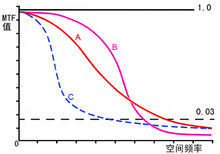
Example of MTF graph
Take the above figure as an example, and perform the following analysis on the three MTF curves of A, B, and C:
The lens represented by curve A has moderate contrast in the low frequency range, but as the spatial frequency increases, its attenuation process is very slow, indicating that its quality is still good.
The lens represented by curve B performs well at low frequencies, indicating that the contrast of the lens is very good, but as the spatial frequency increases, its curve decays quickly, indicating that the resolution of the lens is not very good.
The lens represented by curve C decays quickly at low frequencies, and the overall quality is low.
Different from the above curve, the manufacturer always fixes the spatial frequency and aperture when drawing the MTF curve.
The fixed spatial frequency low frequency (10 line pairs/mm) curve represents the lens contrast characteristics, the higher the curve, the greater the lens contrast. The fixed high frequency (30 line pairs/mm) curve represents the lens resolution characteristics. The higher the curve, the higher the lens resolution. Although the ordinate is still the MTF value, the abscissa is changed to the distance from the center of the image field to the measurement point. The lens is a symmetrical structure centered on the optical axis, and the imaging quality changes from the center to all directions are the same. Due to the influence of aberrations and other factors, the farther a point in the image field is from the center of the image field, the MTF value generally shows a downward trend. Therefore, taking the distance from the center of the image field to the edge of the image field as the abscissa, it can reflect the imaging quality of the edge of the lens.
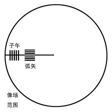
In addition, the MTF value measured by the sinusoidal grating of the line along the tangent direction and the line along the radial direction is different at the position deviated from the center of the image field. The MTF curve generated by the line parallel to the diameter is called the sagittal curve, labeled MTFS (Sagittal), and the MTF curve generated by the line parallel to the tangent line is called the meridian curve, labeled MTFT. As a result, there are generally two MTF curves measured by manufacturers, namely S curve and T curve.
3. Flange distance, back focal length, mechanical back focal length
Rear flange distance refers to the distance from the lens interface to the camera sensor. Back focus refers to the distance from the center point of the last lens of the lens to the camera sensor. The mechanical back focal length refers to the distance between the front end of the lens interface and the camera sensor. The rear flange distance of the CS interface lens is 12.5mm, and the rear flange distance of the C interface is 17.5mm. The CS interface lens can only match the CS interface camera, but the C interface lens can match the CS interface camera by adding a 5mm C to CS adapter ring in addition to the C interface lens.
4. Lens structure: ^6%6~=D%t
6xh/M+JT_$ a, a simple lens composed of single or doublet lens aWq(vw{
Mx*|D!Xz This kind of simple lens only uses a single or doublet lens, so its aberration cannot be perfectly corrected, and the aperture is also small, so it can only be used under strong light. However, due to the extremely low price of such lenses, especially in recent years, optical plastics (pmma) have been widely used instead of optical glass, which makes the manufacturing cost even lower. Therefore, most toy cameras and disposable cameras on the market currently use this simple lens. PQ HH OXB
FW1T b, three three groups of Kirk [cooke] type lens 3g[2O,-
?kH Ogrpr Early Kirk lens composed of three separate lenses, the aperture is located between the lenses, this type of optical structure is the simplest structure that can be preliminarily corrected for lens aberration, and the image quality basically meets the general popular type. The requirements of the camera (lens grade is 2 to 3), and the price is relatively low. In recent years, in order to adapt to the development of automatic and compact cameras, the aperture of the usual three-element Kirk lens has been moved from the middle of the lens to the back of the lens, so that the lenses are in close contact. Due to the dissymmetry of the optical power caused by the rearward movement of the aperture, the system has a large off-axis spherical aberration. As a last resort, the method of blocking the light can be used to ensure the aberration. Therefore, the edge illuminance is relatively low. All need to be considered when using it. GQ2M <
`nS5xep In order to further reduce costs, most of the low-end parallel cameras on the market currently use optical plastic lenses to replace one of the Kirk-type three-element objective lenses (mostly the middle one). At this time, the relative aperture can only be about 1/4.5 . f&2?PTd
Yn;bg 3% c, tessar [tessar] type three groups of four camera lens 3c wt-V[
R0 y{Oo $ The Skystop lens developed by Kirk type is shown in Figure 1-2-18. It originated in Zeiss Optical Factory in Germany in 1902 and was first designed by the famous optical expert Rudolof. It replaces the third element of the Kirk-type lens with a doublet lens group, so the relative aperture of the lens can be greatly improved, and the relative aperture can be 1/3.5~1/2.8 in the case of a medium field of view of 50°~60° . It is currently the most widely used lens structure for mid-range or popular cameras in China. The aperture is located between the second and third groups, forming an asymmetric structure type positive power photographic objective lens. U(%cP#{z
3 E #U5N introduced the cemented lens group to fully improve the astigmatism and off-axis of the objective lens, so it is particularly suitable for landscape photography. p)o*,8D{$9
VrM5aYH<|d, double Gaussian objective lens and its evolution form V]"XZU
A[ S%m!jX> Double Gaussian objective is an objective lens with a larger field of view (about 40°), the relative aperture of which is the first to reach f/2. The initial design is shown in Figure 1-2-19. The addition of two glued surfaces makes it possible to better eliminate aberrations. Although the dispersion of the glass on both sides of the glued surface is different, the refractive index is approximately equal, so the addition of the glued surface has little effect on the monochromatic aberration. The basically symmetrical structure is conducive to the correction of vertical axis aberrations such as coma, distortion, and chromatic aberration of magnification. There is a strong concave lens on both sides of the aperture, which is conducive to the correction of spherical aberration and astigmatism. | T>M
O}H[sH The complicated type of double Gaussian objective is mainly to increase the relative aperture of the lens or to improve the imaging quality of the lens. The most common method is to replace the front or rear positive lens with two single positive lenses, as shown in Figure 1-2-19(a). It can reduce the high-level spherical aberration of the field of view off-axis and the high-level spherical aberration of the on-axis aperture at the same time, and can obtain higher image quality in the case of a larger field of view. Another type of complication of the double Gauss objective lens is to replace the cemented surfaces in the front and back thick lenses with separate curved surfaces; or to divide the front or back positive lenses into two at the same time.
Testing Services


 No.82 Fengze Road, Jiangning, Nanjing City, Jiangsu Province
Copyright(c)2024 Nanjing wave front optoelectronic technology co. LTD. All Right Reserved Powered by:300.cn
